Tutorial - Circuitboard milling with Fabmodules
In this tutorial, you will learn how to use an image of your board design to mill your circuit traces and cut the outline of your board.
* This tutorial might seem a bit long and tedious, but persevere. Once you know how to use an image to mill your circuits, it works like a charm with any type of circuits!
*This tutorial assumes you have experience with circuit design and Eagle. Links to Eagle tutorials are listed.
What you need to download:
- EagleCAD. Free version accessible here.
- GIMP (open source image manipulation software). Download available here.
A- DESIGN YOUR SCHEMATIC IN EAGLE
See tutorial.
B- DESIGN YOUR BOARD IN EAGLE
See tutorial.
C- EXPORT YOUR BOARD DESIGN AS AN IMAGE
Now that your design is ready, you have to export an image of your circuit.
The Fab Modules will use the image of your routes to create the paths for the Roland milling machine.
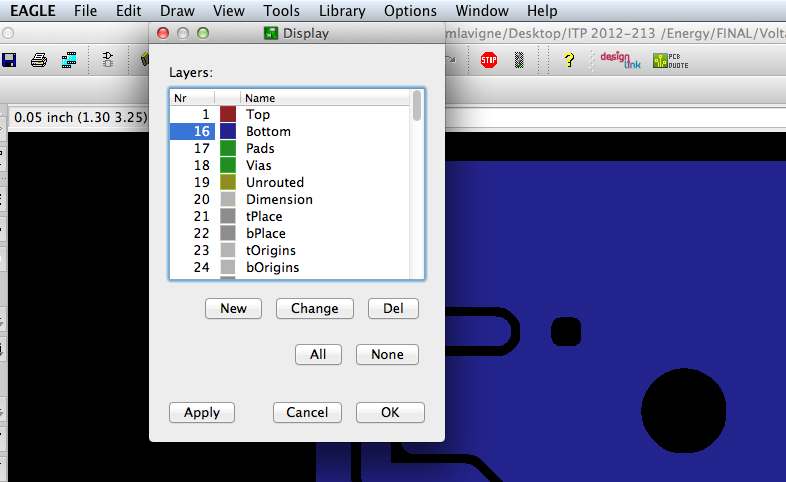
Depending on how you designed you board, export the top or the bottom layer, or both separately in two different .png files.
- Go to view, and select top or bottom.
- Then export as a .png:
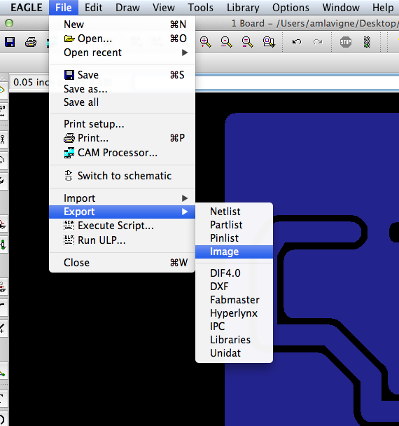
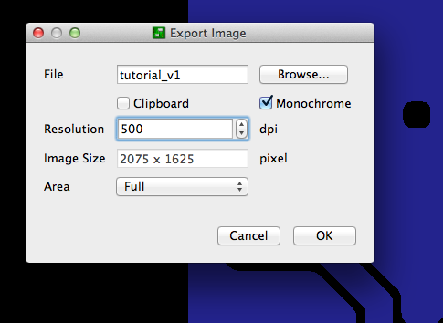
- give a name to your file and select the folder it will saved in;
- select “monochrome” so the .png is only in grayscale colors;
- resolution 500 dpi;
- area Full.
- select “monochrome” so the .png is only in grayscale colors;
- resolution 500 dpi;
- area Full.
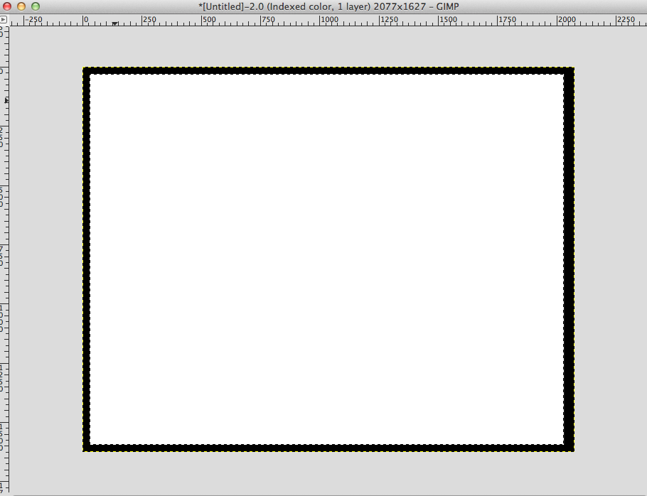
This is how the image of the example circuit looks like:
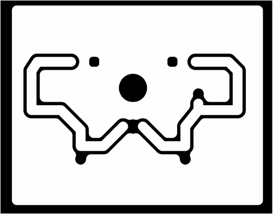
The circuit traces should appear white. Once you process this image in the Fab modules, the Roland will etch out the black and will KEEP THE WHITE.
So Before you continue, make sure your traces are white. If they are black, they will be etched away by the Roland.
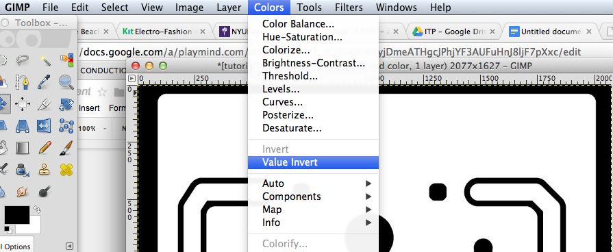
Now we will very and modify the image in GIMP, a convenient free software equivalent to Photoshop if you do not have it.
D- PREPARING YOUR IMAGE FOR THE FAB MODULES IN GIMP (or PHOTOSHOP)
You will now use your image to create two images:
- one for the milling of your board;
- one for the board outline, so the Roland can cut out your board.
1) create an image for the traces.
- open GIMP;
- Open your image;
- The traces of your circuit should be white. If they a
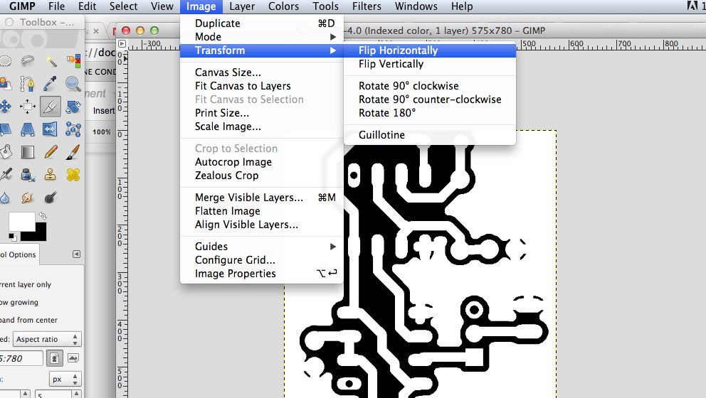
- If your board is a through hole or bottom, you need to flip your image horizontally to mirror your design.
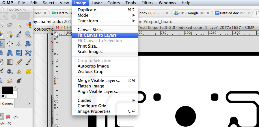
- Now, to make sure the canvas of your image is the same as the board image, you have to adjust the canvas to the image size;
Image→ fit canvas to layers.
Image→ fit canvas to layers.
- You can crop your image, add white text or logos if you want your final board to be decorated/identified with something.
- Export as a .png.
2) Now you have to create another image for the board dimension so the Roland can cut out the outline of your board after milling your traces.
You need to create another image made of a black line for the outside of your board.
- Export as a .png.
2) Now you have to create another image for the board dimension so the Roland can cut out the outline of your board after milling your traces.
You need to create another image made of a black line for the outside of your board.
- Export as a png.
→ save your .PNGs on a usb drive or save them on a cloud service.
E- GENERATING THE FILES FOR THE ROLAND USING THE FAB MODULES
Now that you have your two images :
- one for the circuit traces;
- one for the outline of your board;
You are ready to use the Fab Modules.
The Roland Modela, does not speak normal gcode. It has its own language which is .RML .
MIT has develop an application made of several python dependencies.
The application uses the image of you circuit to generate a .rml file for the Roland. Here is how it works.
- Turn on the Roland;
- Turn on the computer and choose UBUNTU as the operating system;
- Password: redapple
- Save your files on the Roland computer. You can create a file under your name on the desktop.
- Open a terminal window:
- CTRL + ALT + T or;
- Search for Terminal in the Search engine. Top icon on the left of the screen.
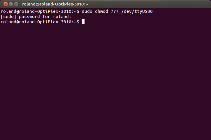
- Once terminal window is open, before we do anything, we will make sure that the computer knows on which port the Roland is connected. To do so, enter the following command in the terminal window:
sudo chmod 777 /dev/ttyUSB0
→ save your .PNGs on a usb drive or save them on a cloud service.
E- GENERATING THE FILES FOR THE ROLAND USING THE FAB MODULES
Now that you have your two images :
- one for the circuit traces;
- one for the outline of your board;
You are ready to use the Fab Modules.
The Roland Modela, does not speak normal gcode. It has its own language which is .RML .
MIT has develop an application made of several python dependencies.
The application uses the image of you circuit to generate a .rml file for the Roland. Here is how it works.
- Turn on the Roland;
- Turn on the computer and choose UBUNTU as the operating system;
- Password: redapple
- Save your files on the Roland computer. You can create a file under your name on the desktop.
- Open a terminal window:
- CTRL + ALT + T or;
- Search for Terminal in the Search engine. Top icon on the left of the screen.
- Once terminal window is open, before we do anything, we will make sure that the computer knows on which port the Roland is connected. To do so, enter the following command in the terminal window:
sudo chmod 777 /dev/ttyUSB0
(If you have an error window, it is probably because the Roland is not turned on. Turn the Roland on and try again.)
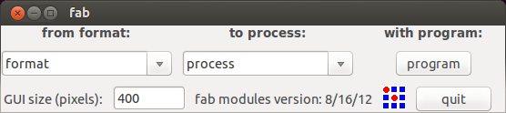
- Then, type:
fab
and press enter.
This window will appear:
- Then, type:
fab
and press enter.
This window will appear:
- In the Format dropdown menu, select .png;
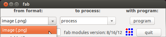
- In the Process dropdown menu, select Roland Modela .rml
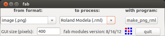
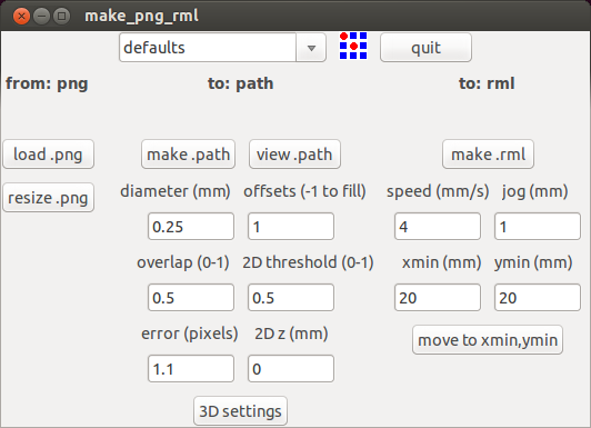
- Press: make_png_rml. This window will appear:
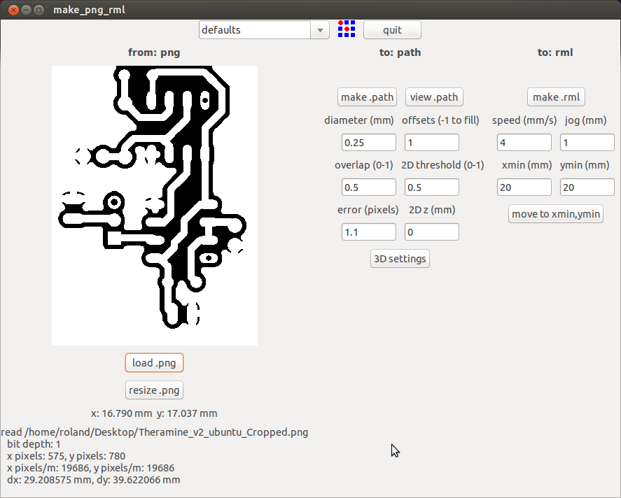
- Load your traces .png file.
- in the “Defaults” drop down menu a the top center, select :
mill traces 1/64
We use 1/64 end bit to mill the traces.
mill traces 1/64
We use 1/64 end bit to mill the traces.
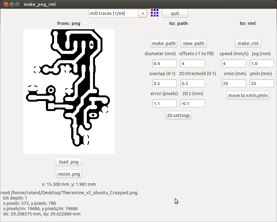
- click on “make path”. The path generated will appear.
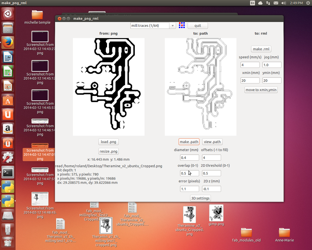
- If you want to have a closer look at your path, click on “view .path”. It will open the Okular dependency and you will be able to see the path in details. When you look at the details of the path, you can see that the traces are created by 4 tiny lines. These lines are defined in the OFFSET setting. When the OFFSET is set to 4, it means that the Roland will mill 4 times the same lines, going each time further and creating an offset from your traces.
- If you would want the Roland to mill out all the copper in between your parts, change the OFFSET settings to -1. You will see that your path has now more lines. The Roland will mill out more copper. Make tests and see what makes more sense for your circuit. Offsetting can take a long time depending on the design of your circuit.
- Once you are happy with the path and the offset setting,
click on “make .rml”, at the top right.
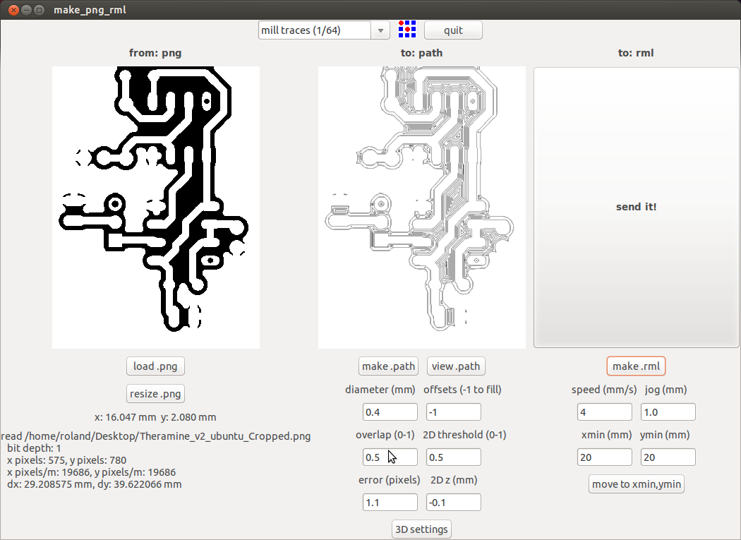
A big button “SEND IT” will appear once the .rml file has been generated.
****DO NOT PRESS ON THE “SEND IT” BUTTON ****
The sending function is corrupted and we do not use it to send the file to the .rml. If you would press on it, the file would be sent to the Roland with errors in the path. We use the Fab modules only to generate the .rml file from the .png
So, now you have generated a path for your circuit traces.
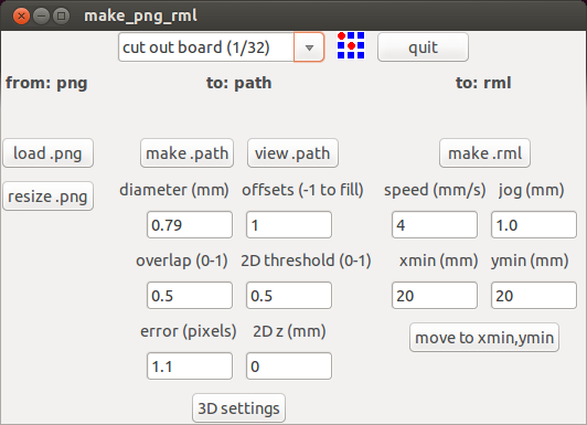
- Repeat the same sequence using your board contour .png.
***Only difference is that in the “default” dropdown menu, choose:
cut out board (1/32)
We use a 1/32 end bit to cut out the board.
****DO NOT PRESS ON THE “SEND IT” BUTTON ****
The sending function is corrupted and we do not use it to send the file to the .rml. If you would press on it, the file would be sent to the Roland with errors in the path. We use the Fab modules only to generate the .rml file from the .png
So, now you have generated a path for your circuit traces.
- Repeat the same sequence using your board contour .png.
***Only difference is that in the “default” dropdown menu, choose:
cut out board (1/32)
We use a 1/32 end bit to cut out the board.
- Now that the Fab modules have generated the two .rml files:
- one for the traces;
- one for cutting the board;
You need to save those file on your USB key. The fab modules save them in the Home directory:
- one for the traces;
- one for cutting the board;
You need to save those file on your USB key. The fab modules save them in the Home directory:
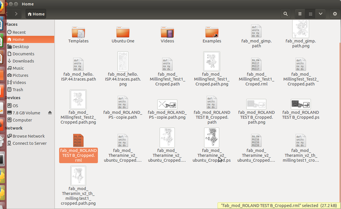
Put your files on your USB key.
- Close all the windows.
- Turn off the computer.
- Turn on the computer assigned to the Roland and chose to operate it with Windows7 (not Ubuntu).
- Password : redapple
- Save your files in a folder under your name on the desktop.
F-PREPARE ROLAND FOR MILLING
See tutorial here.
G-SET REFERENCE POINT
See tutorial here.
H- SENDING THE FILES TO THE ROLAND
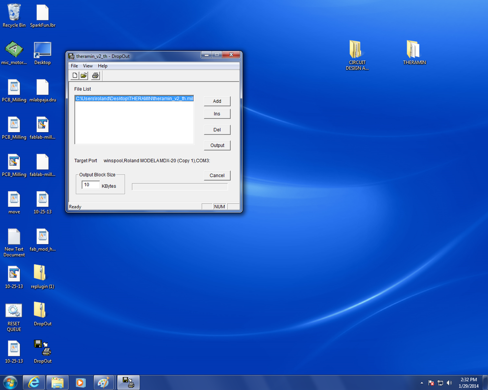
We use an application called DropOut to send the files to the Roland. The icon is on the bottom left of the screen.
- Close all the windows.
- Turn off the computer.
- Turn on the computer assigned to the Roland and chose to operate it with Windows7 (not Ubuntu).
- Password : redapple
- Save your files in a folder under your name on the desktop.
F-PREPARE ROLAND FOR MILLING
See tutorial here.
G-SET REFERENCE POINT
See tutorial here.
H- SENDING THE FILES TO THE ROLAND
We use an application called DropOut to send the files to the Roland. The icon is on the bottom left of the screen.
Then press “RUN”:
You will send your files one at a time in this order:
You will send your files one at a time in this order:
- the .rml file to mill the traces first with the 1/64 bit. Once the job is done:
- Change to the 1/32 bit and send the .rml file to cut the outline of the board